Machine AI GPU server liquid cooling manifolds: select tools for pockets, sealing faces, ports and threads. Review inspection needs and request a KYTOOLS quote.
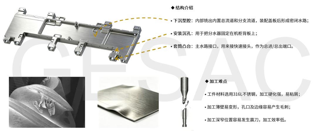
AI GPU server liquid cooling manifold machining turns a coolant distribution design into a component with controlled sealing faces, ports, cavities and threads. In cold-plate liquid cooling systems, a manifold connects supply and return piping with multiple cooling branches serving GPU or CPU cold plates. This KYTOOLS guide focuses on the machining and tooling decisions behind those features; the approved drawing defines material, dimensions, sealing and cleanliness requirements.
How GPU server liquid cooling requirements translate into machining
| Component requirement | Relevant machining work | What to specify or inspect |
|---|---|---|
| Sealed connections | Finish sealing faces and control port dimensions and burrs | Drawing-defined flatness, surface finish and sealing geometry |
| Multiple cooling branches | Drill ports, tap or mill connection threads | Port positions, hole quality and thread-gauge acceptance |
| Internal passages and cavities | Rough pockets, clean corners and evacuate chips | Minimum radius, depth, remaining stock and internal burrs |
| Assembly and cleanliness | Inspect, deburr and clean the finished manifold | Dimensions, cleanliness and specified leak or pressure tests |
Start with the manifold drawing and material
Record material grade, stock condition, overall length, support locations, cavity depth, minimum internal radius, sealing faces, ports and thread specifications. Do not infer a stainless grade such as 316L from a component image. A long manifold may require distributed support, while thin walls and open cavities require a clamping sequence that preserves the final inspection datums.
Tool selection across the machining sequence
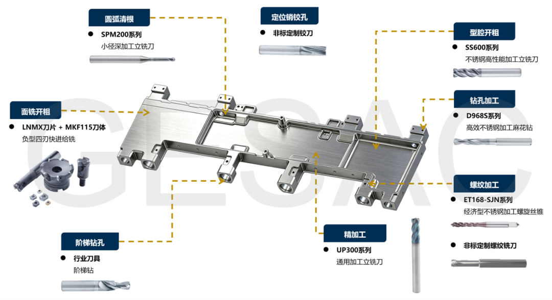
| Operation | Tool category to evaluate | Process and acceptance check |
|---|---|---|
| Face roughing | High-feed indexable milling where the setup permits | Insert engagement, available power, support and datum allowance |
| Pocket roughing | Carbide end mill matched to the specified material | Chip evacuation, tool reach, residual stock and wall stability |
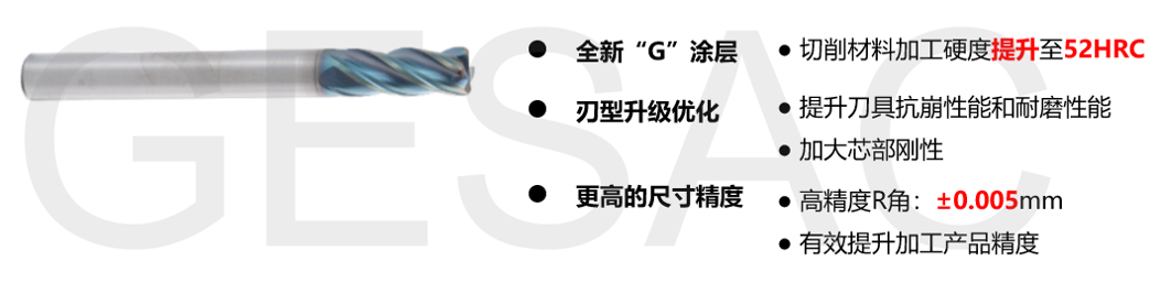
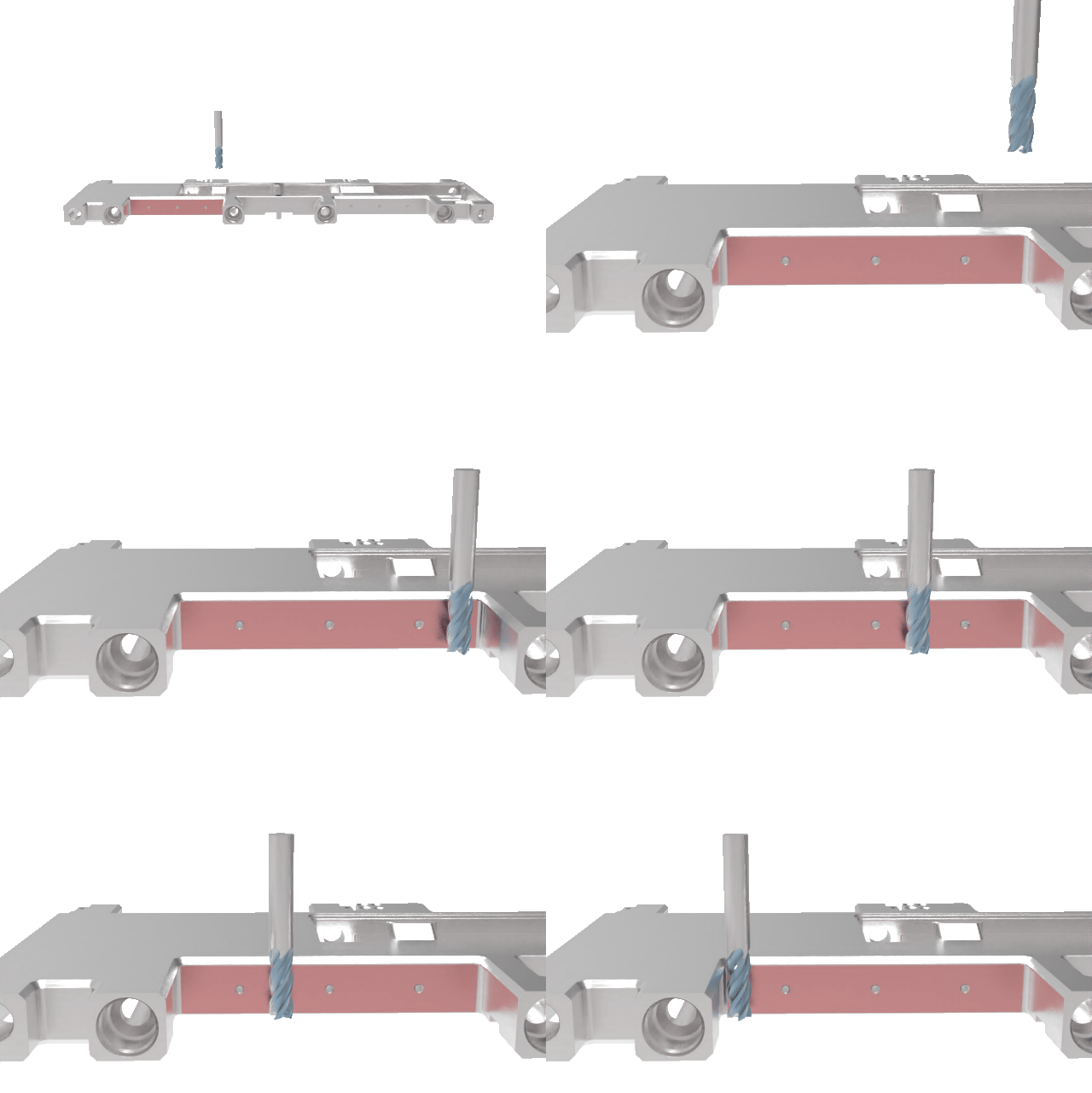
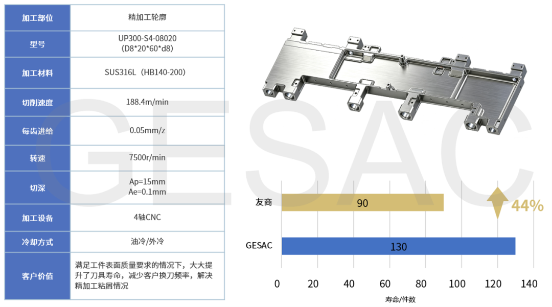
| Finishing | Finishing end mill with controlled runout | Uniform allowance, sealing-face finish and dimensions after unclamping |
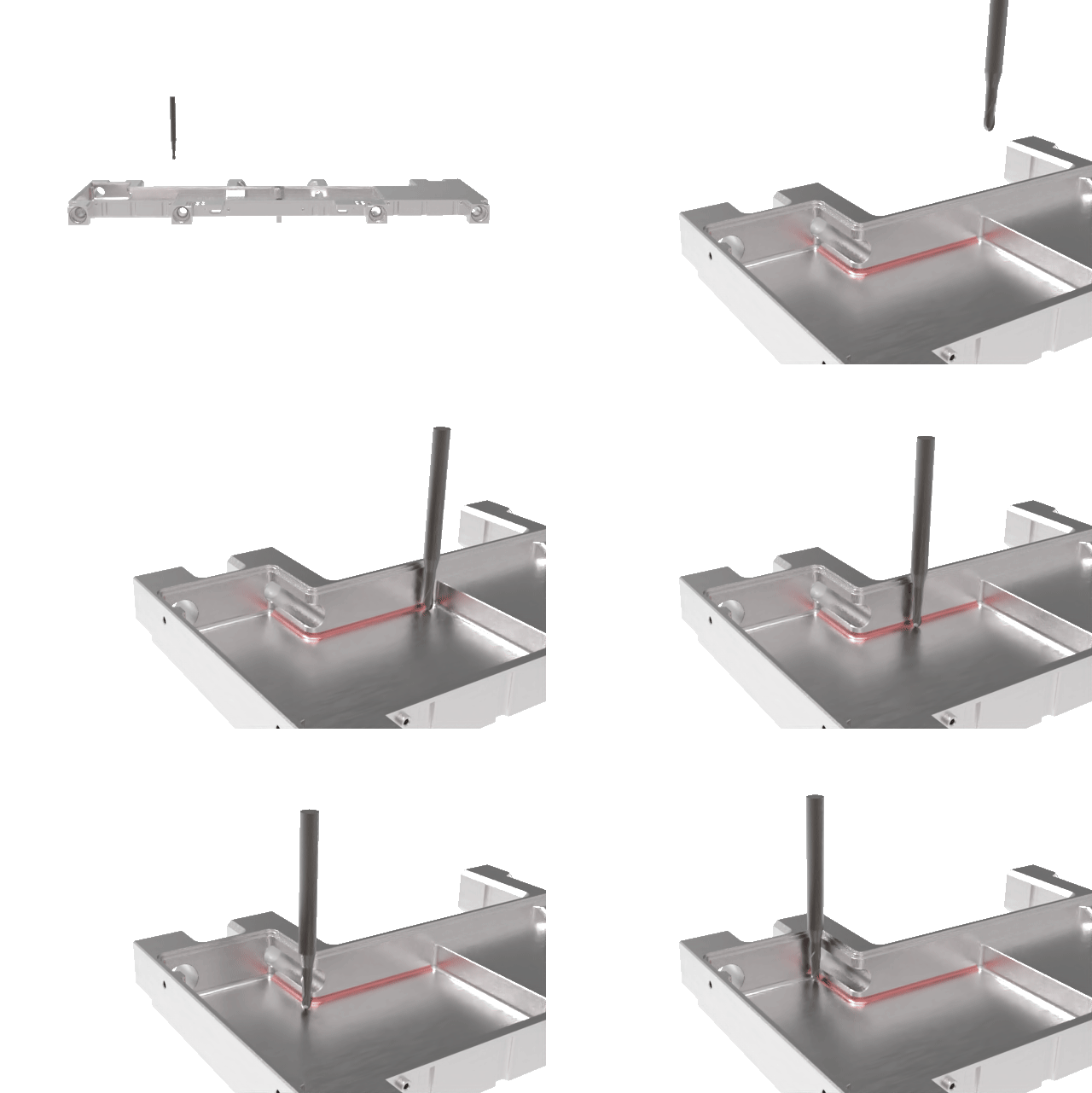
| Internal-corner cleanup | Small-diameter or relieved-neck carbide end mill | Minimum radius, usable neck length, deflection and corner stock |
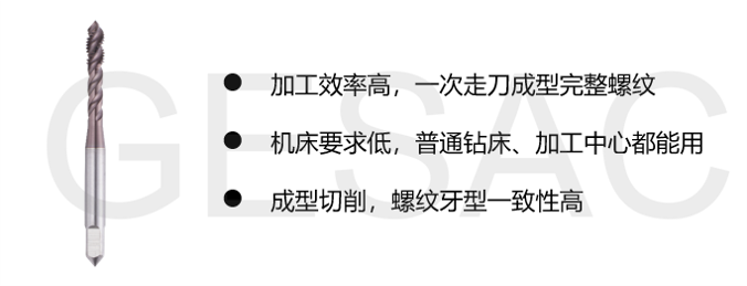
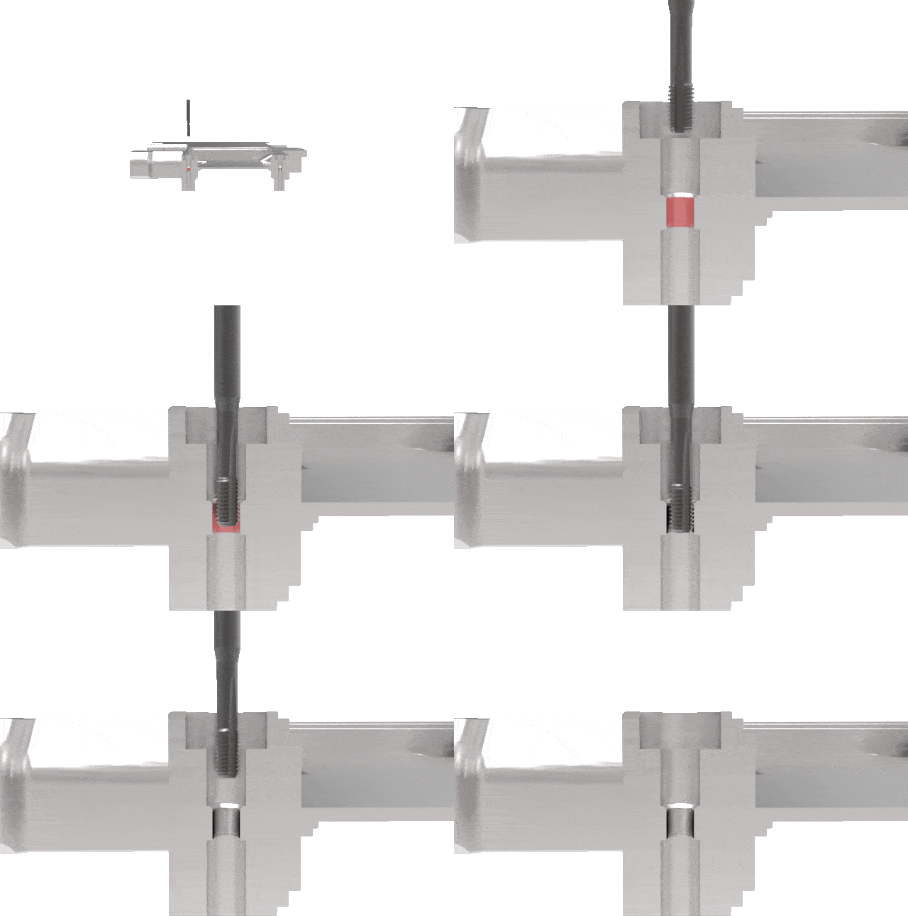
| Tapping | Material-specific spiral-flute tap where suitable | Drilled-hole quality, chip evacuation, synchronization and thread gauging |
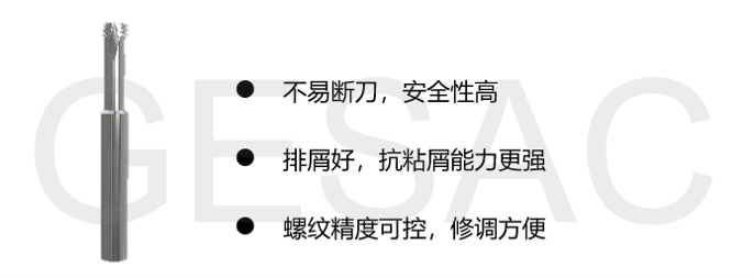
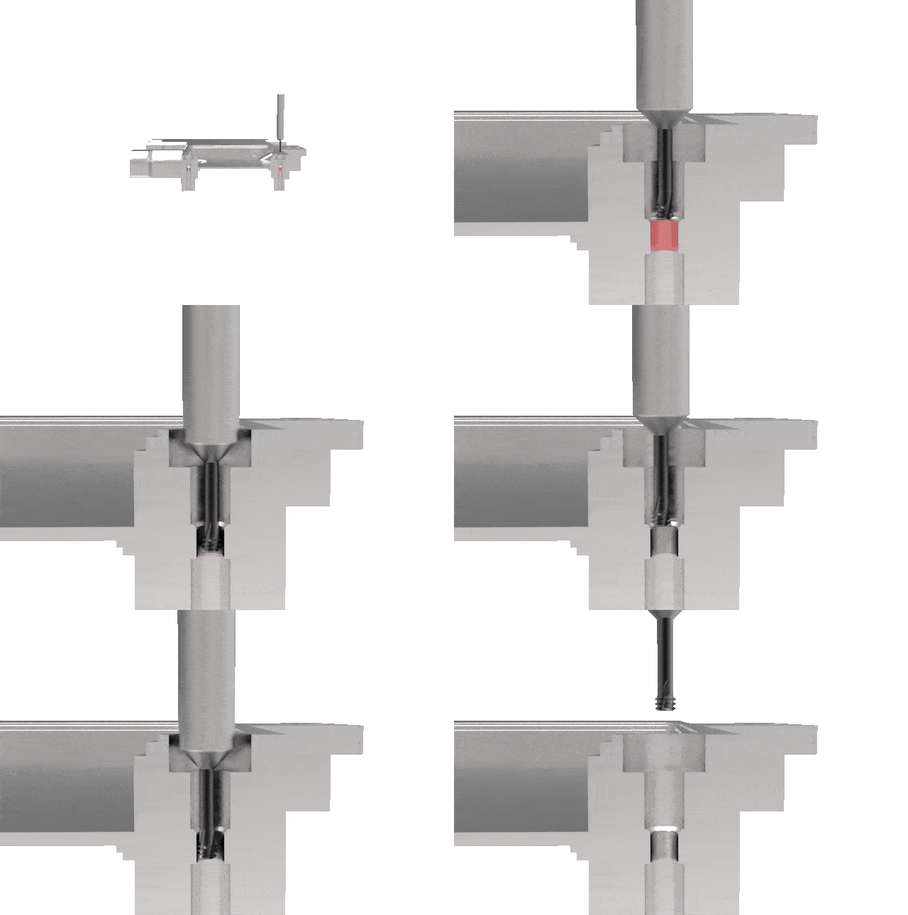
| Thread milling | Thread mill selected to the drawing | Thread form, pitch, internal clearance and machine interpolation |
Face roughing: build a stable datum
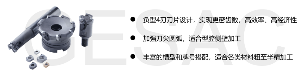
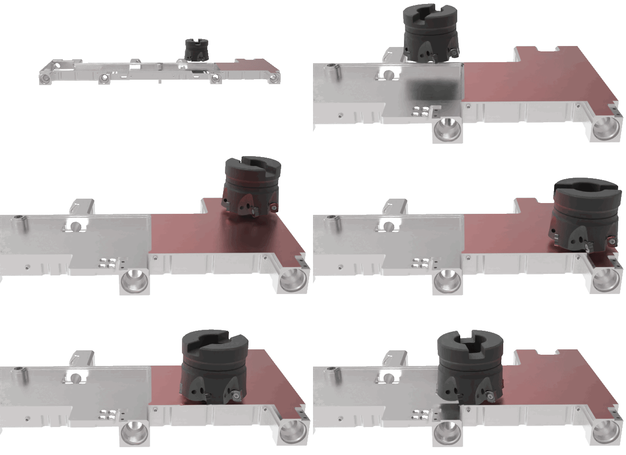
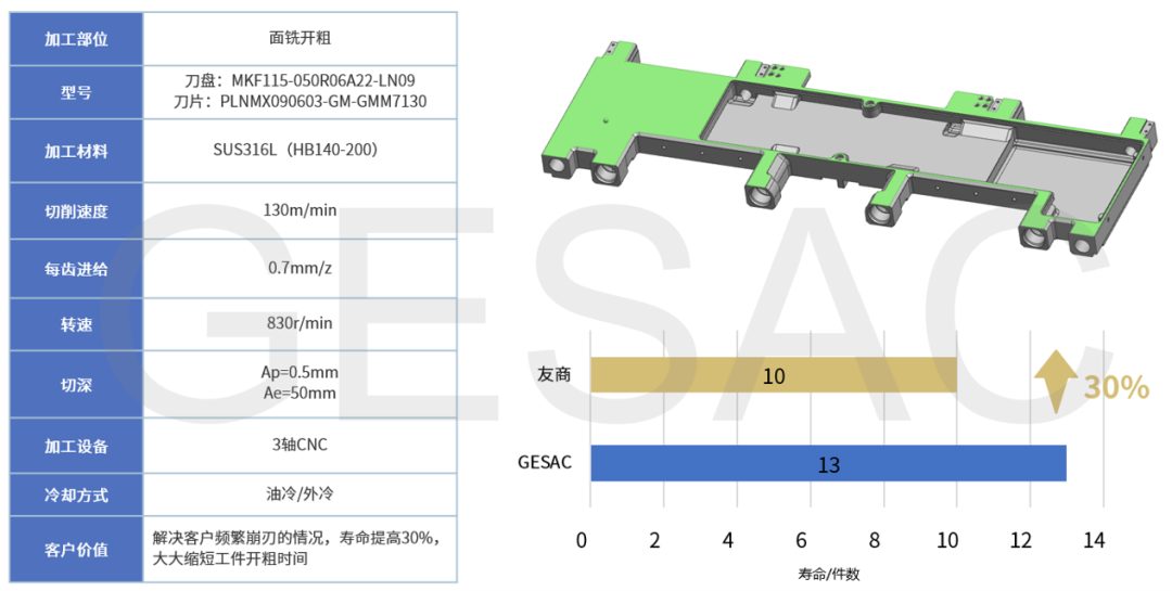
Evaluate high-feed face roughing only after confirming cutter clearance, insert engagement, spindle capability and support under the cut. Keep a planned finishing allowance on functional faces. A specific insert code in a reference illustration does not establish an interchangeable KYTOOLS part.
Pocket roughing: manage engagement and chips
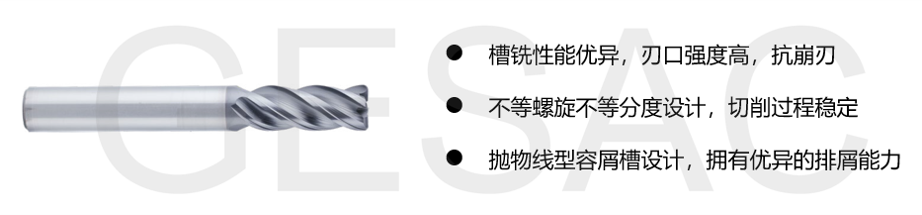
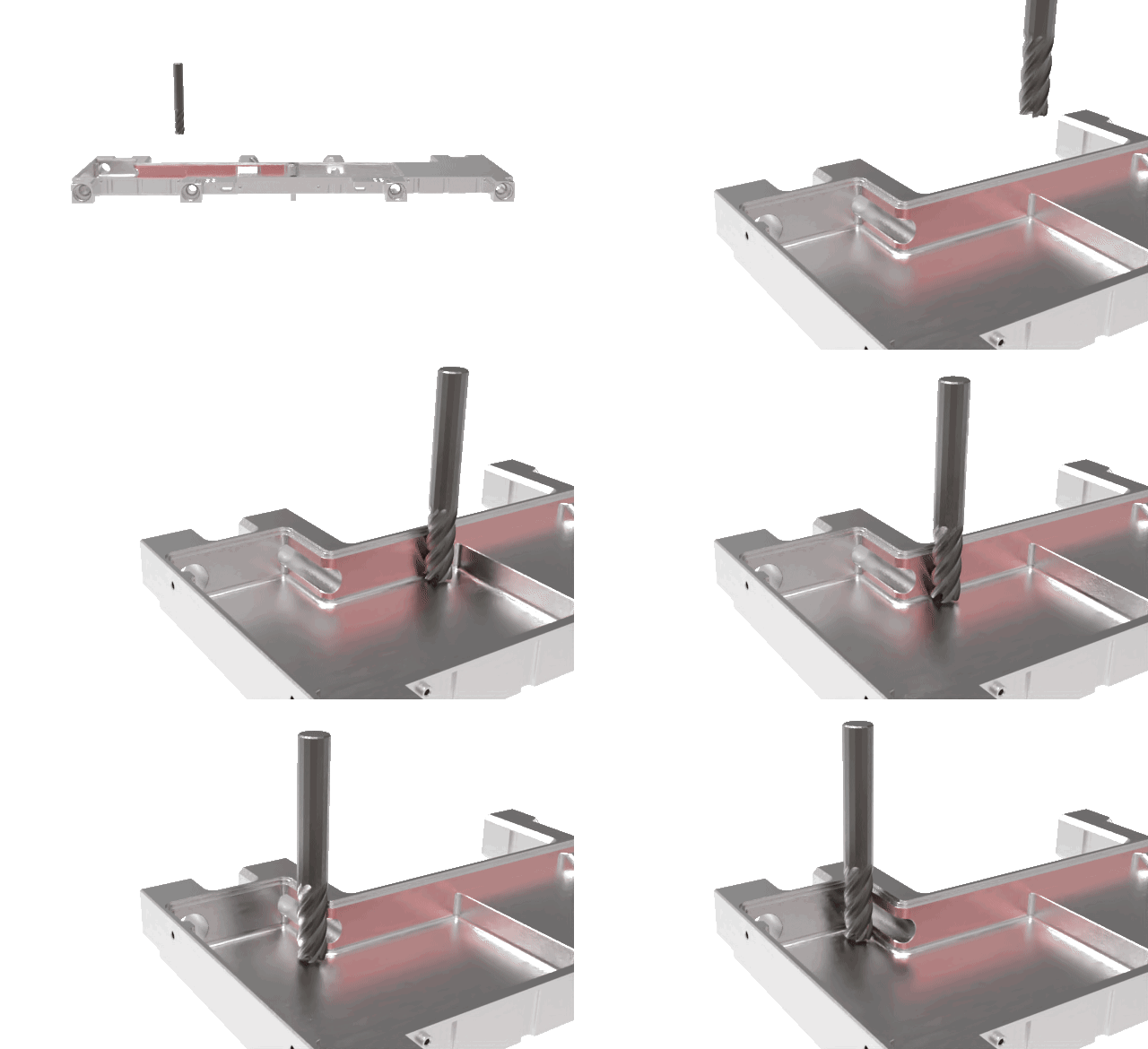
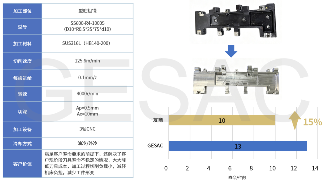
Select the roughing end mill for the actual work material, pocket depth and available coolant. Use a path that controls engagement and avoids trapping chips in deep channels. Leave consistent stock for finishing rather than asking a long finishing tool to remove uneven roughing stock.
Finishing: control allowance and runout
Finish critical faces and cavity walls with controlled holder runout and predictable allowance. Separate dimensional acceptance from the appearance of a machined surface: the drawing determines flatness, surface finish and sealing-feature requirements. Check relevant dimensions after releasing the fixture.
Corner cleanup: use the shortest workable reach
Use a smaller diameter only where the drawing requires it. Check neck relief, holder clearance and the full tool envelope at the deepest corner. Lower rigidity and uneven corner stock can make a long small-diameter tool unstable; review the preceding roughing path before increasing the tool reach.

Tapping: prepare the hole before the thread
Select tap geometry for the material and for a blind or through hole. Confirm pilot diameter, usable thread depth, bottom clearance, coolant and machine synchronization. Define acceptance with the specified thread gauge; the source does not establish a universal tapping speed or torque.
Thread milling: confirm clearance and interpolation
Check that the thread mill fits inside the prepared hole and can produce the specified form and pitch with the available interpolation. A custom cutter requires a thread drawing and an agreed inspection method. Choose between tapping and milling by feature access, machine capability and qualification requirements.
Qualify the whole process, not only the cutting time
Measure datum consistency, wall and port dimensions, sealing-face condition, burrs and thread acceptance. Where required by the customer specification, include pressure or leak testing and a documented cleaning check after machining. The source reports a component cycle below nine hours in its own setup; this is a third-party case result, not a KYTOOLS cycle-time promise. Establish a baseline on your machine before comparing productivity.
Liquid cooling manifold machining FAQ
Does every liquid cooling manifold use the same material?
No. Confirm the drawing and material certificate. Stainless steel, aluminium and other specified materials require separate tooling and process decisions.
Can the source cutting parameters be copied to another machine?
Treat them as a reference only. Material condition, tool construction, holder, reach, fixture, coolant and machine limits must match before any parameter can be transferred or validated.
What should a KYTOOLS enquiry include?
Send KYTOOLS your AI GPU server liquid cooling manifold drawing, diameter list, material, port threads, pocket depth, coating, trial quantity and annual demand for a tooling quotation.
Prepare a KYTOOLS tool enquiry
Reference article and original illustrations
Tags